Solidworks Part Drawing Move Body
TheSOLIDWORKS 'Move/Copy Body' command is an efficient manner to get a model reoriented properly for a variety of downstream uses.
When working with imported Step, IGES, or Parasolid imported geometry, there might be a need to reorient the model. Unlike a native SOLIDWORKS model, your choices for modifying the orientation of the imported model are express. You cannot just modify the sketch aeroplane of the outset characteristic and endeavour to fix it so easily.
The 'Move/Copy Body' feature tin be used reorient geometry to the default planes. This will brand information technology easier to locate in assemblies. Reorienting a office can also help with drawing view cosmos or with making mold tooling.
how to Access the "Move/Re-create Body" Feature
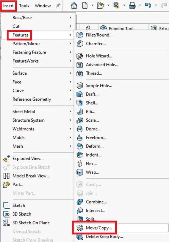
The Motion/Copy Torso feature is not located in the Control Managing director Features Tab. In the Features drib-downward menu, navigate to Insert > Features > Movement/Copy…
This feature works with both solid and/or surface bodies. Bank check the 'Solid' and 'Surface Bodies' folder in the FeatureManager Design Tree to get a ameliorate understanding of what blazon of geometry you are working with. This will prove y'all how many solid or surface bodies are in a native SOLIDWORKS file or an imported model.
When using the 'Movement/Copy Body' feature, start select the solid or surface trunk(s) to move. Select the desired body(s) from the graphics area or from the Solid or Surface Bodies folders. Every bit shown below, ensure the "Re-create" option is unchecked so that y'all only move the geometry and not indistinguishable it.
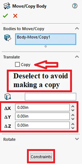
Highlighted above in the lower 2 cherry boxes are the two ways to move the bodies, Translate/Rotate or Constraints. The 'Constraints' selection is very like to using the standard assembly mates. Simply as when mating components in assemblies, three mates/constraints tin fully define the orientation of prismatic bodies.
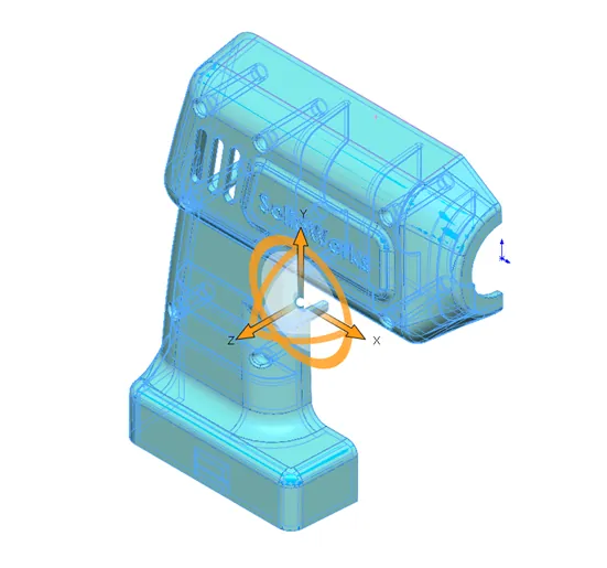
The Interpret/Rotate pick will show a large, orange triad (shown beneath) that can exist used to dispense the orientation of bodies. The geometry tin can exist manipulated by dragging the arrows or circles or by entering values into the dialog boxes. You tin can interpret in multiple directions in ane pace or feature but you lot cannot translate and rotate in the same feature.
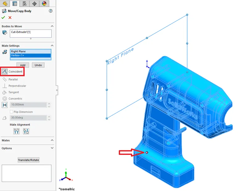
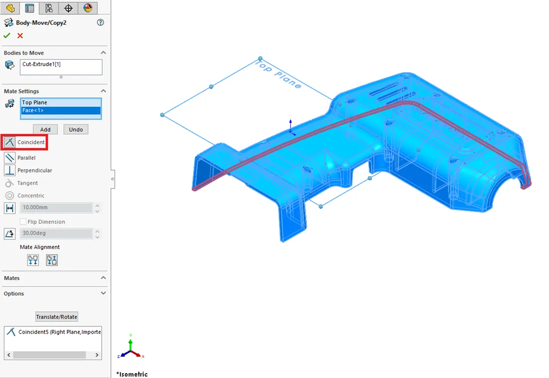
In this case, we use the 'Constraints' option with three default planes and a combination of geometry entities to get the desired orientation, moving the origin into the lower left-hand corner. Pace 1 uses the Correct Plane and lower back vertex as shown below.
Step ii will rotate the model 90 Degrees. This can be done in several ways. Ane intuitive way is to utilise the 'Constraint' option with a bottom face up making it Ancillary to the Height Plane as shown below.
You lot can add several 'Constraints' in the same command, just remember to select 'Add together' to lock in each constraint.
The final step shows that you tin use the Origin equally a indicate for one of the constraints just like in a regular assembly mate. This final action gets the origin placed in the lower-left corner.
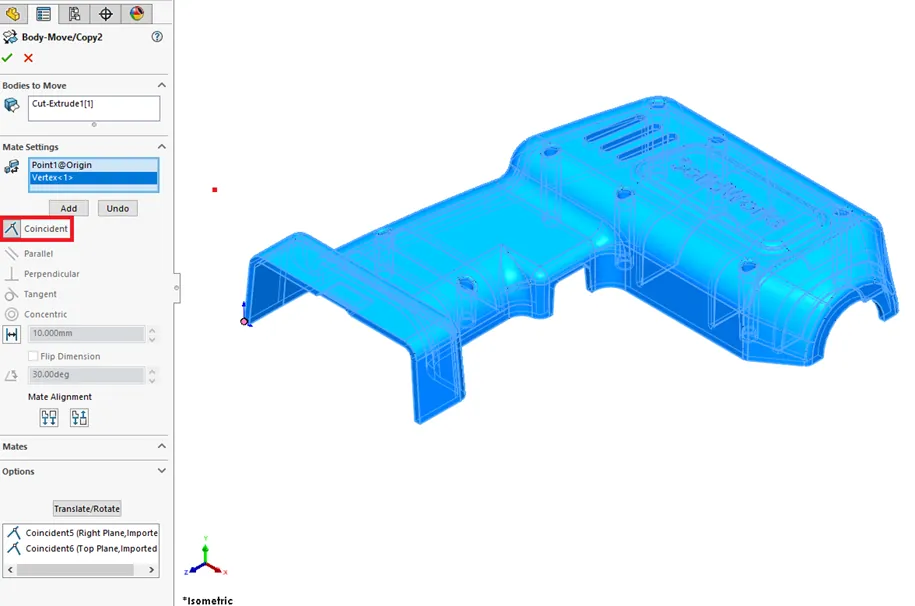
The Front Airplane could have also been used for this stride. Vertices or edges can be used when a apartment face might non ever be available. Later on selecting 'Add' for the third fourth dimension, this locks in all three 'Constraints' into one 'Motion/Copy Body' characteristic. This characteristic acts as a point in time and can exist modified past selecting 'Edit Feature'.
Motility/Re-create Torso Limitations
As mentioned above, the 'Move/Copy Torso' characteristic will not allow you to translate and rotate in the same stride or command. The proficient news is those types of orientation changes can easily be broken up into multiple features.
The concluding thing to know is that 'Move/Copy Body' does not allow a combination of reference geometry as constraints to be added in an imported role. If you lot see this warning "Delight select an entity from one of the moving bodies" select a vertex, edge, or face if possible. You will not be able to use an centrality or reference plane with another plane for constraints.
In other words, you lot can only employ ane reference plane and an edge, face, or vertex. Worst instance scenario would be to utilize a combination of constraint and interpret/rotate 'Movement/Re-create Torso' features to get the desired orientation. Another workaround might exist to add a small extrusion and employ a face, border, or vertex from that geometry and then remove the actress geometry with a cut or 'Delete Face' command.
Conclusion
The SOLIDWORKS 'Motion/Copy Body' feature can be used multiple times and can exist suppressed/unsuppressed manually or in configurations. As mentioned before, this control works with both solid and surface bodies and can be used to duplicate geometry similar to the 'Linear Design' feature. This control can help quickly reorient your imported models for easier assembly, drawing or mold tooling cosmos, or CAM setup.
Our Newest SOLIDWORKS Tutorials
Link a Dimension to the BOM with a Custom Property
Searching for Functions in SOLIDWORKS 2021
How to Install and Troubleshoot Fonts in SOLIDWORKS
Virtual Components: Parts that Aren't Parts
Dimension Precision Settings: Leading and Trailing Zeroes
Source: https://www.goengineer.com/blog/using-solidworks-move-copy-body-feature
0 Response to "Solidworks Part Drawing Move Body"
Post a Comment